2. Creating 3D Models with Computer Aided Design#
OpenSCAD#
1. Initial Reference and Collaborative Contribution#
To get started, I initially checked Victor De Pillecyns’ page and it helped me understand the structure I wanted and provided inspiration for some of the parameters.
I used a portion of Victor De Pillecyn’s work as a basis for creating the parameters and getting started with my design. Specifically, I used the following code segment:
``` difference() { hull() { cylinder(h = 10, r = 4, center = true); translate([0, 8, 0]) cylinder(h = 10, r = 4, center = true); } cylinder(h = 10, r = 3, center = true);
I also referred to the [OpenSCAD cheatsheet](https://openscad.org/cheatsheet/) as a guide while working on the different functions and operations.
Additionally, this 3D model is inspired by the FlexLink Satellite beam available on [Thingiverse by BYU_CMR.](https://www.thingiverse.com/thing:5157921) This design was created by Thingiverse user BYU_CMR and is licensed under Creative Commons - Attribution - Non-Commercial.
### 2. Parameter Setup
I then set up the key parameters to control the dimensions of my model.
radius_outer = 4; radius_inner = 3; height = 10 / 2; // 5 (half height) distance = 8; distance2 = 16;
bar_width = 2; // Width of the connecting bar bar_height = height; // Height of the connecting bar bar_length = 2 * distance2; // Length of the connecting bar
Declaring these parameters like ```radius_outer```, ```radius_inner```, and ```height``` helped ensure consistency throughout my code. It also made it easy for me to modify dimensions when needed, which is super useful for creating a parametric model.
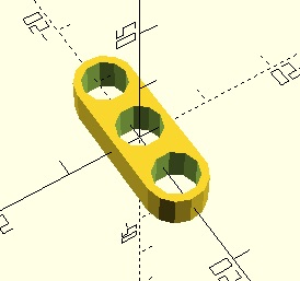
### 2. Creating the Outer Cylinders Module
I created a module to generate the outer cylinders.
``` module create_outer_cylinders(radius, height, distance, distance2) {
hull() {
cylinder(h = height, r = radius, center = true);
translate([0, distance, 0]) cylinder(h = height, r = radius, center = true);
translate([0, -distance, 0]) cylinder(h = height, r = radius, center = true);
translate([0, distance2, 0]) cylinder(h = height, r = radius, center = true);
translate([0, -distance2, 0]) cylinder(h = height, r = radius, center = true);
}
}
I used the hull() function to create a smooth shape around the cylinders. I defined their positions using distance and distance2 to create the desired pattern. Making this a module allowed me to easily reuse it in other parts of the code.
3. Creating the Inner Cylinders Module for Subtraction#
Next, I added a module for subtracting inner cylinders from the outer structure.
``` module subtract_inner_cylinders(radius, height, distance, distance2) { cylinder(h = height, r = radius, center = true); translate([0, distance, 0]) cylinder(h = height, r = radius, center = true); translate([0, -distance, 0]) cylinder(h = height, r = radius, center = true); translate([0, distance2, 0]) cylinder(h = height, r = radius, center = true); translate([0, -distance2, 0]) cylinder(h = height, r = radius, center = true); }
I mirrored the positions of the outer cylinders for the inner ones, allowing me to subtract them from the main structure and create a hollow interior.
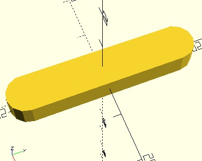
### 4. Adding a Connecting Bar
I added a module to create a connecting bar along the X-axis.
module connecting_bar(length, width, height) { translate([20, 0, 0]) { cube([length, width, height], center = true); } }
The connecting bar was designed to link the different parts of the model, adding stability. By using ```cube()``` and specifying its dimensions, I was able to place it precisely where I needed it with the help of ```translate()```.
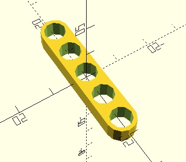
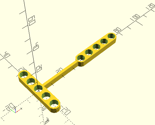
### 5. Main Union Operation
I combined all the components using a ```union() ```operation.
```union() {
// Perform the difference operation for the main structure
difference() {
create_outer_cylinders(radius_outer, height, distance, distance2);
subtract_inner_cylinders(radius_inner, height, distance, distance2);
}
// Attach a straight connecting bar along the X-axis
connecting_bar(bar_length, bar_width, bar_height);
}
Using union(), I combined the different parts into a single object. The difference() operation was used to subtract the inner cylinders from the outer ones, creating the hollow sections. This ensured all elements fit together properly.
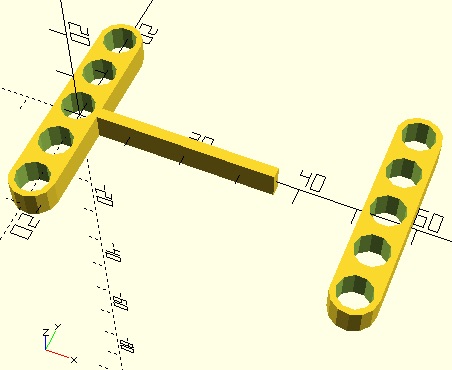
6. Adding a Rotated and Translated Structure#
I added another instance of the main structure, rotating and translating it to create symmetry.
translate([55, 0, 0])
rotate([0, 0, 90])
union() {
    // Perform the difference operation for the main structure
    difference() {
        create_outer_cylinders(radius_outer, height, distance, distance2);
        subtract_inner_cylinders(radius_inner, height, distance, distance2);
    }
}
This step involved translating the structure along the X-axis and rotating it by 90 degrees.
License#
This work is licensed under a Creative Commons Attribution-NonCommercial 4.0 International License.
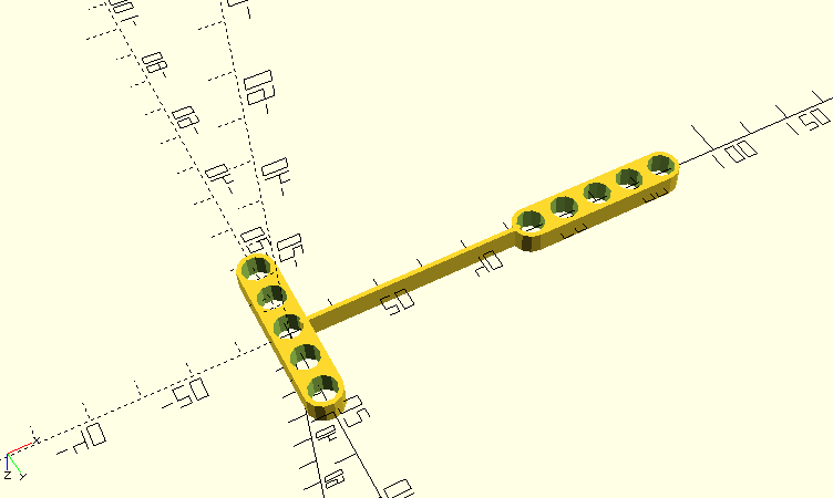
This is the result of my final code in which I modified. Refer to my Module 3 to find more about the changes and why I made changes.
// Bendlink by Calirie Kate Plamenco is marked with CC0 1.0.
// To view a copy of this license, visit https://creativecommons.org/publicdomain/zero/1.0/

// Parameters
radius_outer = 4;
radius_inner = 3;
height = 10 / 2;
distance = 8;
distance2 = 16;


bar_width = 1;   // Width of the connecting bar (modified to make it thinner)
bar_height = height; // Height of the connecting bar
bar_length = 49; // Adjust length to fit the model (extended length for better flexibility)

// Module for Creating Outer Cylinders
module create_outer_cylinders(radius, height, distance, distance2) {
    hull() {
        cylinder(h = height, r = radius, center = true);
        translate([0, distance, 0]) cylinder(h = height, r = radius, center = true);
        translate([0, -distance, 0]) cylinder(h = height, r = radius, center = true);
        translate([0, distance2, 0]) cylinder(h = height, r = radius, center = true);
        translate([0, -distance2, 0]) cylinder(h = height, r = radius, center = true);
    }
}

// Module for Subtracting Inner Cylinders
module subtract_inner_cylinders(radius, height, distance, distance2) {
    cylinder(h = height, r = radius, center = true);
    translate([0, distance, 0]) cylinder(h = height, r = radius, center = true);
    translate([0, -distance, 0]) cylinder(h = height, r = radius, center = true);
    translate([0, distance2, 0]) cylinder(h = height, r = radius, center = true);
    translate([0, -distance2, 0]) cylinder(h = height, r = radius, center = true);
}

// Module for Connecting Bar along the X-axis
module connecting_bar(length, width, height) {
    translate([27, 0, 0]) { // Modified position to improve attachment
        cube([length, width, height], center = true);
    }
}

// Main Operation
union() {
    // Perform the difference operation for the main structure
    difference() {
        create_outer_cylinders(radius_outer, height, distance, distance2);
        subtract_inner_cylinders(radius_inner, height, distance, distance2);
    }

    // Attach a straight connecting bar along the X-axis
    connecting_bar(bar_length, bar_width, bar_height);
}

//
translate([70, 0, 0])
rotate([0, 0, 90])
union() {
    // Perform the difference operation for the main structure
    difference() {
        create_outer_cylinders(radius_outer, height, distance, distance2);
        subtract_inner_cylinders(radius_inner, height, distance, distance2);
    }


}
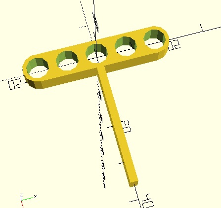
Resulting to this 3d Model with a more flexible bar.
Here are the files to my creation:
Lessons Learned#
One important lesson I learned is that it’s crucial to do an initial test run of the code and print the actual design before finalizing. This helps identify potential issues early, such as compatibility. Since I didn’t have a LEGO block on hand, I couldn’t confirm if my design was actually compatible with LEGO, which would have been an important validation step.L