3. 3d Printing#
1. Download PrusaSlicer#
I went to PrusaSlicer the download page, downloaded the version for macOS, and followed the installation prompts to complete the setup.
Follow the installation prompts to complete the setup.
2. Configuration and Setting Changes#
All the information that I used change the settings are here.
Complete the initial setup wizard:
I Selected the 3D printer model: Original Prusa i3 MK3S & MK3S+ with a 0.6mm nozzle.
I then set up the filament type and other basic configurations as prompted by the wizard.
by Navigating to the “Printer Settings” tab to fine-tune the printer settings:
Adjusted parameters like layer height, infill density, and print speed to match the requirements of my construction kit.
Ensured the nozzle size matches the specifications of the printer (0.6mm).
I also went to the “Filament Settings” tab:
then Choose the filament type: PLA.
3. Importing My 3D Model#
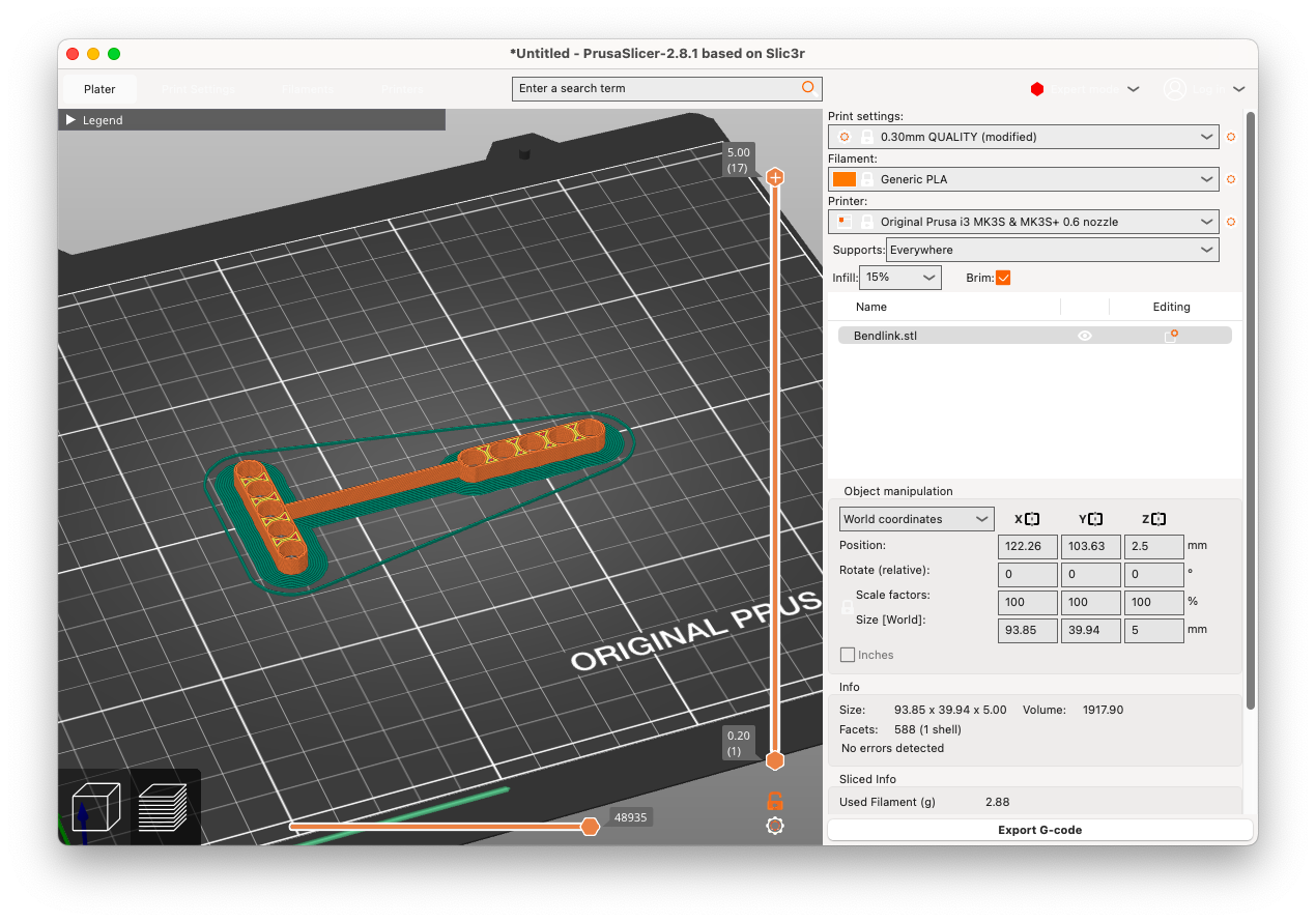
I clicked “Add” to import my 3D model file (in STL format), placed the model on the virtual print bed, and ensured it was properly oriented for optimal print quality.
4. Setting Up Supports and Brim#
Under the “Print Settings” tab, I set Supports to Everywhere to support any overhangs in the model and enabled Brim to help with bed adhesion, especially for smaller parts.
5. Slicing the Model#
I clicked “Slice Now” to generate the G-code for my 3D model and reviewed the sliced preview to check for potential issues like unsupported overhangs or areas that needed adjustment.
6. Exporting G-code#
Once I was satisfied with the slicing, I clicked “Export G-code” to save the G-code file. I saved it to my computer or directly to an SD card for printing and labeled the file clearly.
7. Post-Processing and Evaluation#

Once printing was complete, I carefully removed the print from the print bed.
I evaluated the print quality, focusing on flexibility, layer adhesion, and overall accuracy.
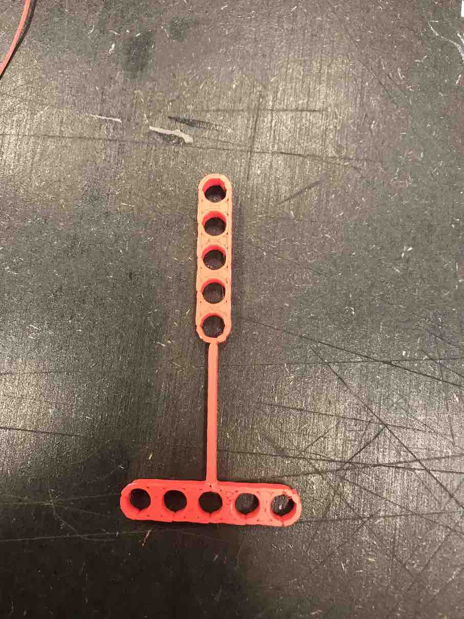
8. Modifications Done#
After 3D printing this model, I found that it was not flexible enough. The connecting bar ended up being a bit stiff and shorter than I anticipated, which affected the overall flexibility of the design. That’s why I modified the parameters of the bar, making it longer and thinner, and then adjusted the location and attachment of the two attachments to improve flexibility.
Changes Made During Modification#
Bar Parameters: Modified bar_width to make it thinner (from 2 to 1) and adjusted bar_length to make it longer (from initial value to 49). This change was aimed at improving the flexibility and reach of the connecting bar.
bar_width = 1;   // Width of the connecting bar (modified to make it thinner)
bar_height = height; // Height of the connecting bar
bar_length = 49; // Adjust length to fit the model (extended length for better flexibility)
Position Adjustment: Updated the translate() values for the connecting bar to better align with the model, particularly changing the translation to [27, 0, 0] for improved attachment.
// Module for Connecting Bar along the X-axis
module connecting_bar(length, width, height) {
    translate([27, 0, 0]) { // Modified position to improve attachment
        cube([length, width, height], center = true);
    }
}
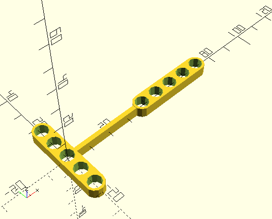
Resulting to this 3d Model with a more flexible bar.
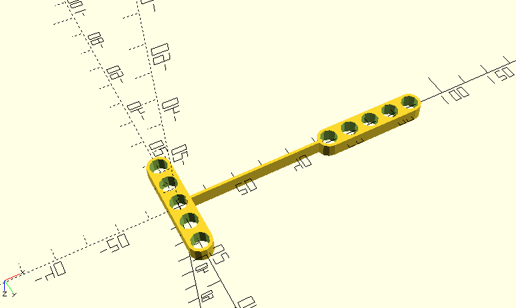
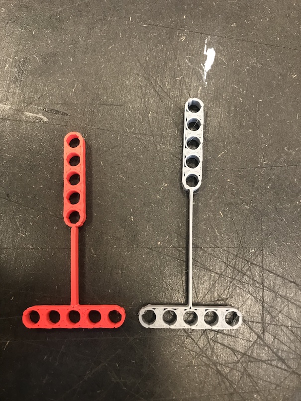
and here is a comparison of both: